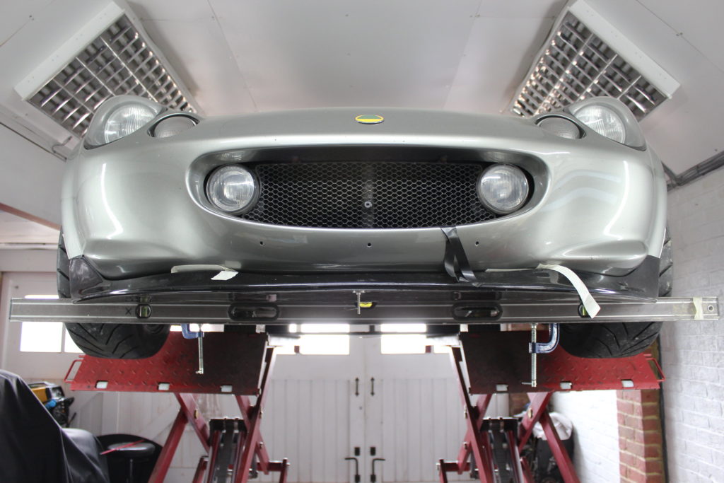
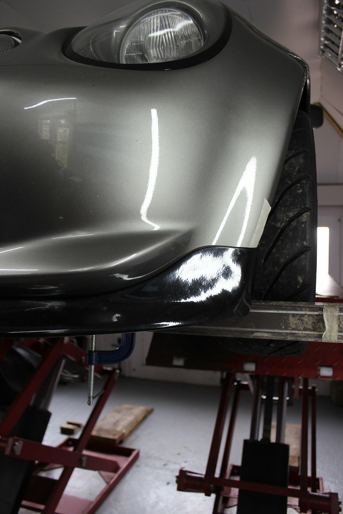
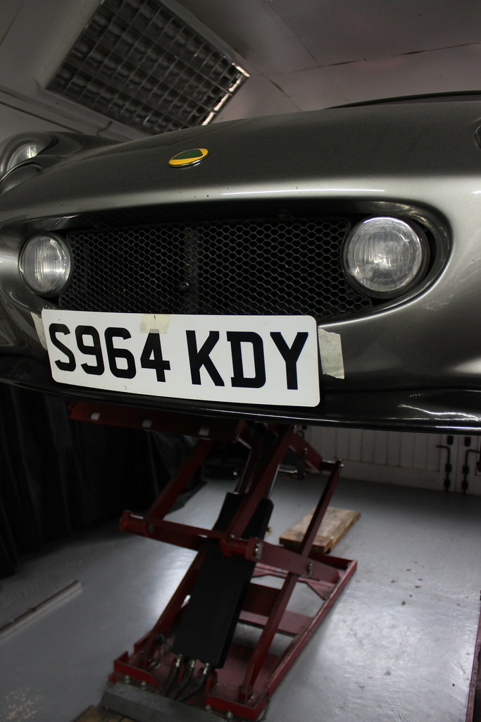
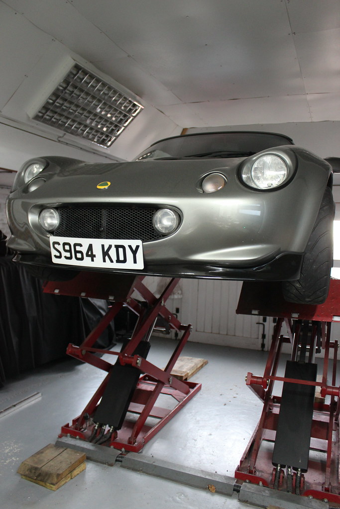
After the suspension refresh I did a full wheel alignment and eventually got to doing the corner weights (more on that another time). When going round the car, checking the ride height I also kept an eye on how the bodywork sat in relation to the floor particularly as the front was now a bit lower. I noticed something wasn’t right. The front splitter was wonky! It was way lower on one side than the other. I don’t know which previous owner fitted it but I guess they had their eye’s closed or no access to a tape measure when they did it???
The splitter was never going to be a perfect fit given that it just isn’t a perfect fit for the clam but that’s pretty much the norm for aftermarket fibreglass panels. It could definitely fit better than it was though. It had basically not been fitted centrally meaning one side had pulled up a bit high and the other side couldn’t fit up as high as it should have.
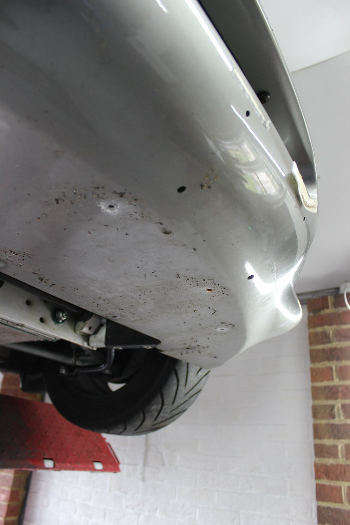
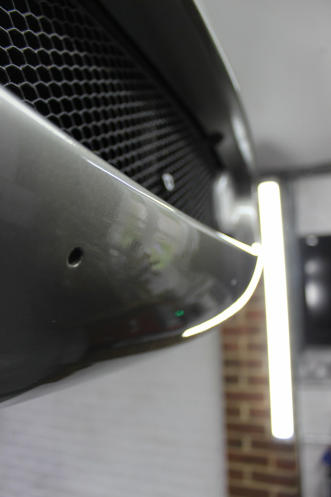
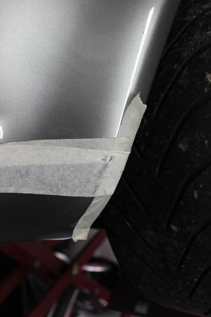
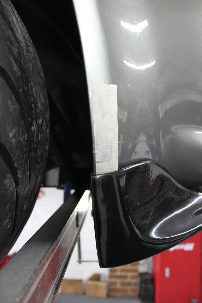
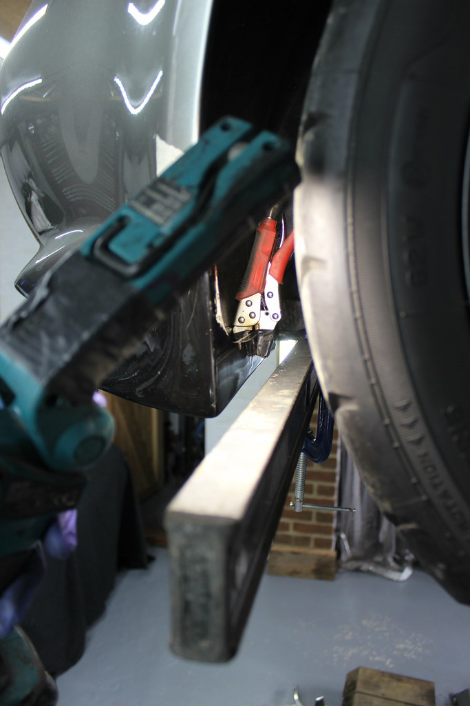
Here the pictures show the rear of the splitter where it’s fitted at the front of the wheel arch and you can see how it’s not symmetrical.


There was no way I could leave it like that now I’d seen it so off it came.


Number plate and fixings off too.


A good clean of the paintwork that was hidden and…
…the splitter too.

First off, find some new fixing from the various I keep in stock.
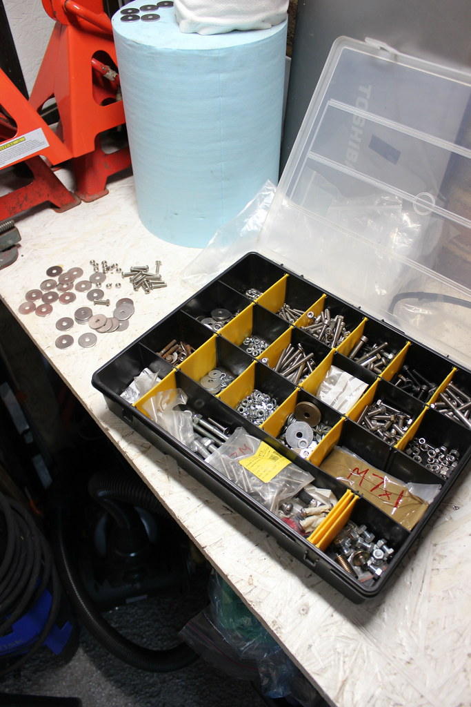
All stainless steel nuts, bolts and washers.

I put some masking tape on the front clam where the splitter touches to prevent any damage while offering it up.
This made it pretty clear where the fit was tight.
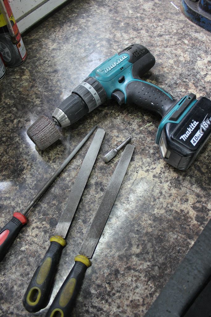
Using a heat gun I was able to reshape the splitter a little to help it fit a bit better.

I also filed an sanded some areas to help give a better fit to the clam.
As there were already some holes drilled in the underside of the clam I elongated the middle hole in the splitter allowing me to fit it up in place but slide it from side to side and get it in a central position.

Clamping a long level up to the crash structure gave a perfect straight edge, level to the chassis to line the splitter up to.


Some masking tape with matching measurements marked on each side also helped.

After a fair bit of shuffling around and measuring and checking I was happy and used some clamps to hold the rear fixing sections in place.

Nice and even each side and about as good as it’s going to get for something that is imperfect from the start.

I had some spare rubber edge strip left over from something else so fitted some lengths of it where the splitter touches the clam. This should prevent any paint damage.


New holes for the new fixings.

All new holes drilled and stainless fixings in place.

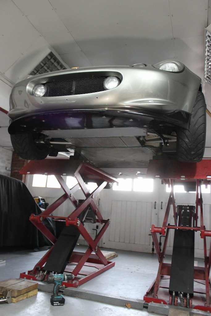

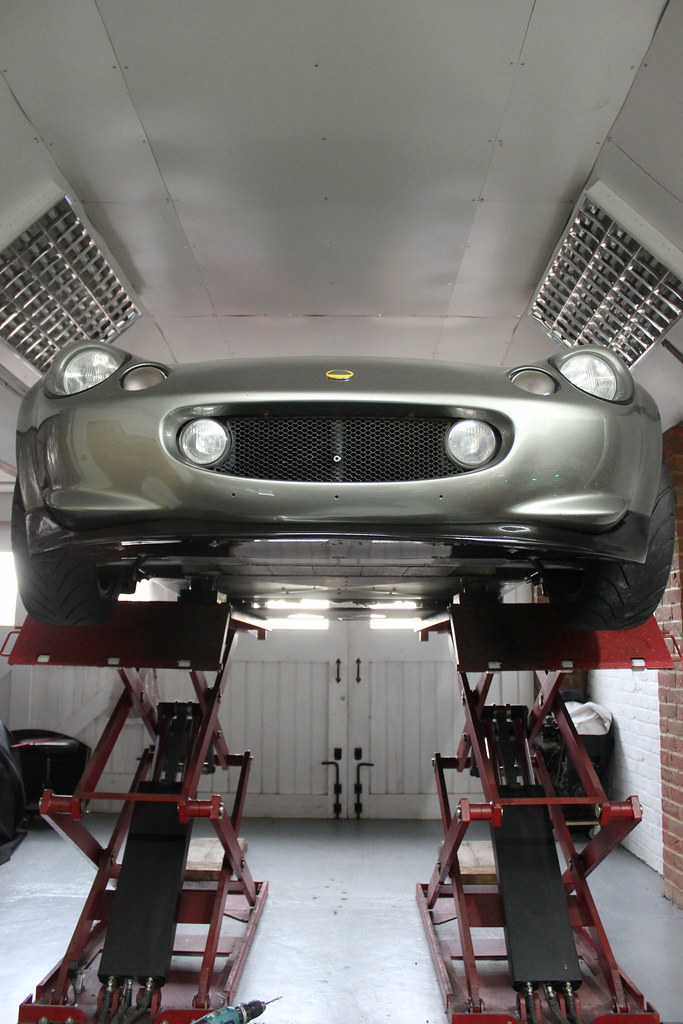
Done, much better.

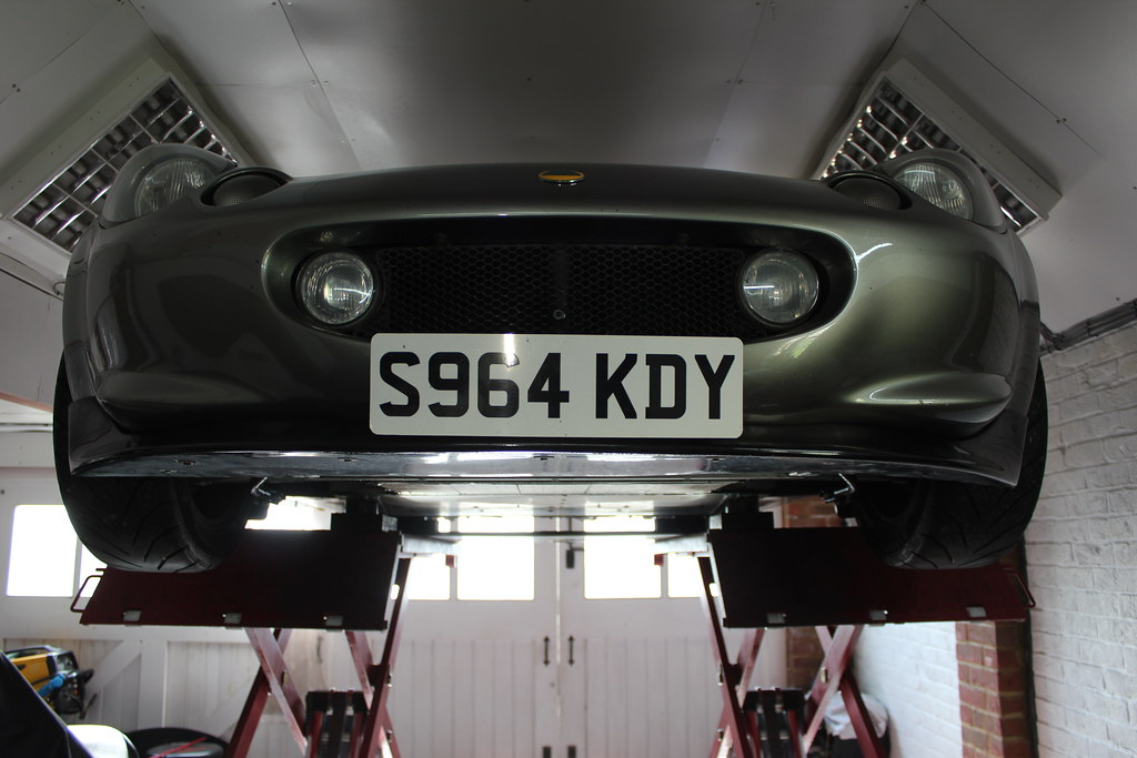
Better put the number plate back on.

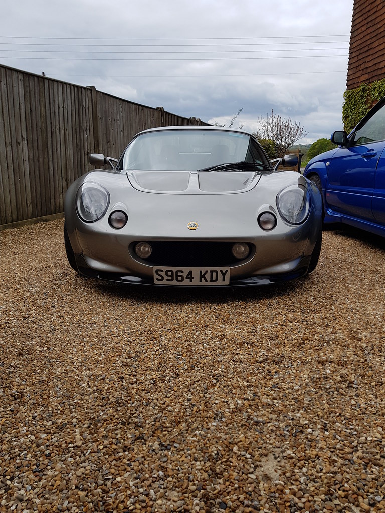
No more wonky splitter! 🙂