(First posted on MX5 nutz forum in April 2016)
Having received my ECU Master DET3 I then had to figure out how to wire the thing in. Like I said I couldn’t find any mx5 specific info for wiring a DET3 but there are example wiring diagrams in the DET3 manuals and obviously there’s plenty of info on mx5 wiring and ECU pinouts so it just needed matching the two.
In my search I did find a guy running a DET3 on his supercharged mx5 engined MGB so I asked him if he had any info on how he’d wired his. He sent me a link to a wiring diagram he followed that worked for him. It was pretty much the same as the manuals general example shows so that gave me confidence what I was planning should work. Check out his build here: http://retrorides.pr…simply-enjoying
So with an idea how the DET3 wants be be wired and this useful mk1 mx5 pinout diagram a mate and I got started.
Found the ECU in the usual place 
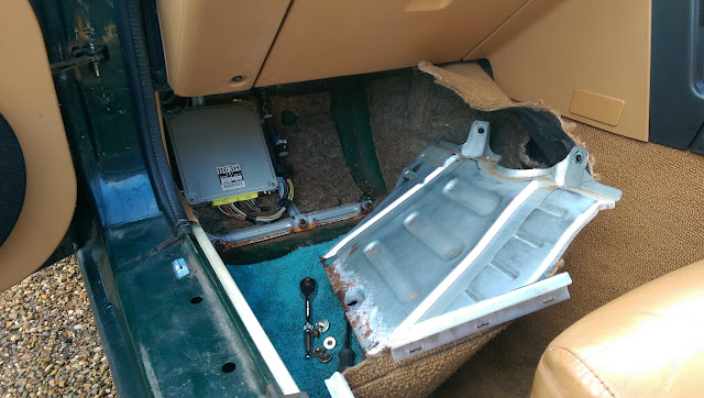
DET3 and mx5 pinouts

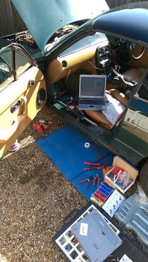
Checking everything gives the expected voltages before chopping wires

Power to the DET3 wired in so we could check the software communicated ok and update the firmware on the DET3 to the latest version.
Firstly we intercepted the CAS signal to the ECU. After getting the correct 4 pulse per 720 crank degrees set in the software the engine ran fine. I got my mate to adjust the timing while I used a strobe at the engine to check the DET3 was doing exactly what he’d asked it to (all with the wire connected in the diagnostics port to prevent the ECU adjusting the timing itself).
All was good so we moved on to splicing wires off to the DET3 for coolant and air intake temperature and intercepting the MAF sensor.
I used some scotch lock connectors that accept a spade connection for splice connections. They’re never all that great though so I soldered them too.

One or two little problems slowed progress down like not having the DET3 in the correct setting to use the map switch as a 5V sensor input. It says it quite clearly in the instruction manual but I just missed it. Also killing the original ignitor by leaving the ignition on 2nd click all day. New one was only 30 quid though the hassle of finding the problem was a pain.

I ran a hose through from the inlet manifold for the MAP sensor too. It now sits quite neatly like so


Battery on the old laptop lasts about 10 mins so had to fetch mine out of the house to be able to go anywhere. Anyway, the log tab shows the sensors read sensible values and the ECU is happy as the car drives fine with the DET3 connected though its not actually changing anything yet. It’s simply replicating the outputs just as they come in for now.

So far so good but I’m still a long way off getting the supercharger back on. I hope to sort out the MAF to MAP conversion and find a suitable IAT sensor to replace the one in the standard MAF. It will need to have a similar resistance/temp profile to the Mazda one as the ECU will still need it.
If I can get the engine running ok using the MAP sensor then I might try moving on to running the standard injectors directly off the DET3 to have a go at making my own fuel map with the standard engine. Or I could simply get some larger injectors in and try making them run on the standard engine with the DET3 still running in the piggyback mode. We’ll see how it goes.
This is how I initially wired the DET3 (now I’ve deleted the MAF I have my wideband wired into the map switch input).

You can’t change the analogue input allocations when in Fuel Implant Mode so this is how the inputs must be wired to make sure the software labels the inputs correctly.