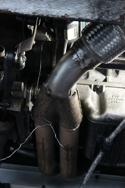
When I first got the Elise I found a number of exhaust leaks so spent some time replacing gaskets to sort them out. More about that here and here. While doing this I noticed the outer braiding of the flex section had started to break and the lambda sensor didn’t look great. Clearly someone had attempted to remove the sensor before and failed as the edges of the hex were rounded. I also didn’t remove the manifold to replace the manifold to head exhaust gasket. So I added these things to my list of jobs but not too high up as they could wait to be looked at when the Elise was off the road for winter.

Well now I had finished some winter restoration work on the rear end of Jem’s Mini, the Elise was back in the working side of the garage and spring hadn’t yet arrived, it was time to pull the exhaust off again and come up with a plan for the manifold and downpipe.
I say ‘come up with a plan’ but I sort of already had one though I didn’t know if it was possible. This was my plan…
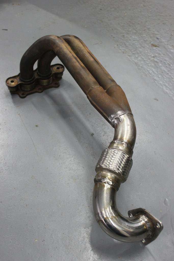
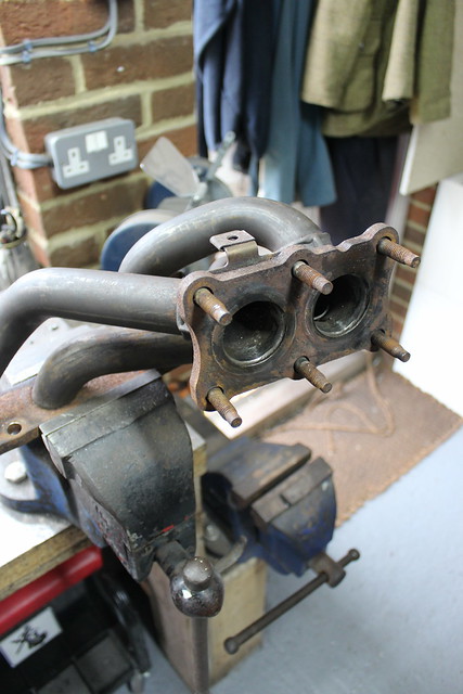
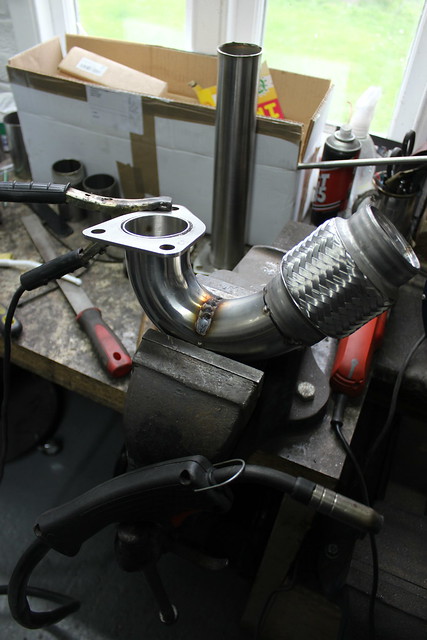
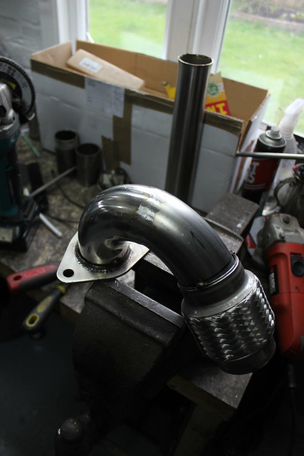
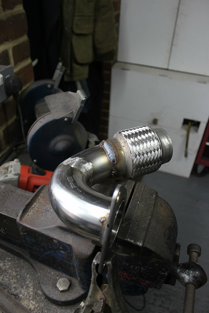
A 160 VVC manifold and downpipe from an MG ZR160. I’ve had this a while as it came with a donor engine for my Mini. The manifold is the same as was fitted to the S2 Elise and VVC models so I knew that would fit, the downpipe I wasn’t so sure about.
These manifolds are an improvement as they have a 6 bolt flange so should be less prone to leaking as I found the current 4 bolt flange to be. This one also has a flexi section incorporated into the joint between the manifold and downpipe and the lambda sensor is in a far easier to reach position. The other improvement in this arrangement is that the 2 to 1 join happens further down the downpipe and uses larger diameter pipe. Minimal improvements in the grand scheme of things but every little helps and I already had this sitting around so why not use it.
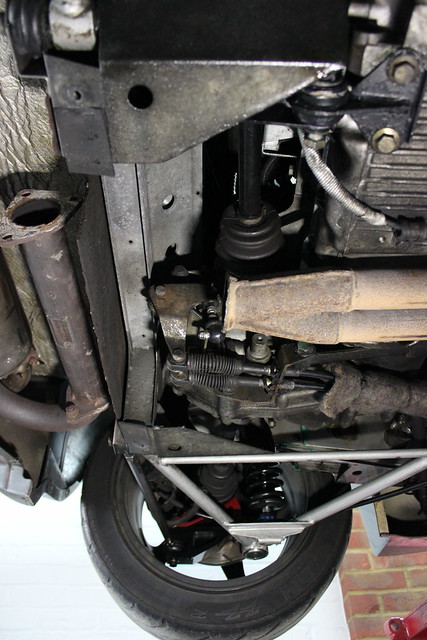
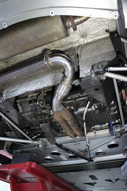
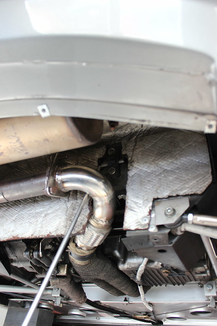
Obviously this exhaust wasn’t just going to be a bolt on job, I would need to make a section to join this to the usual join at the cat/de-cat. So I removed the existing manifold and downpipe to cat/de-cat section to eye up the new plan.
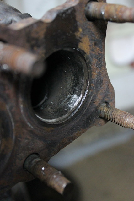
Here I’ve removed the downpipe, now the manifold can come off but this was made more difficult than it should be by the fact there was no way the lambda sensor was coming out first, to aid removal. I didn’t even waste any time trying to remove it, clearly someone had attempted that pretty seriously before, given the mess it was in.

With the heat shield removed…
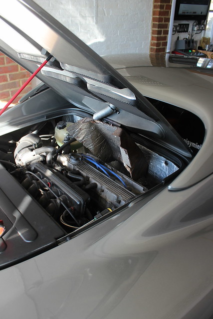
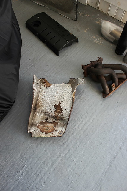
…and the gearbox mount undone to give some engine wiggle room…

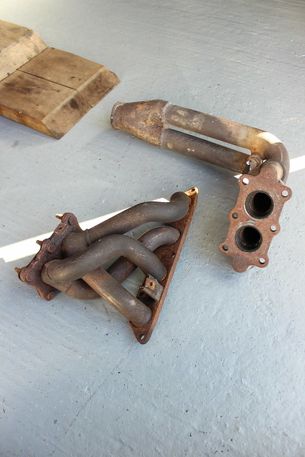
…the manifold came out.

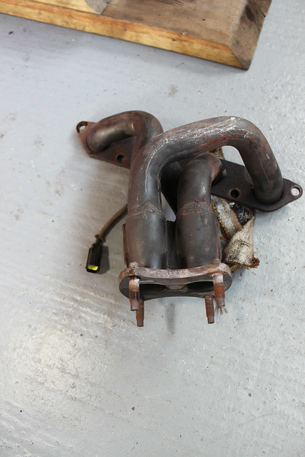
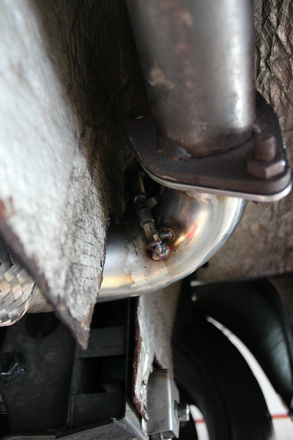
No chance I was gonna get a spanner on this to remove it!

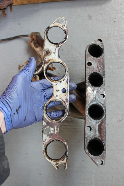
I think there may have been a couple of small leaks in the manifold gasket.


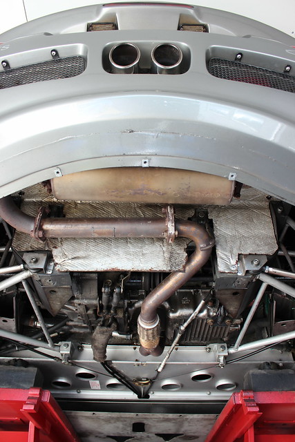
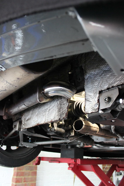
With that lot out of the way I could offer up the 160 exhaust and see how it looked.

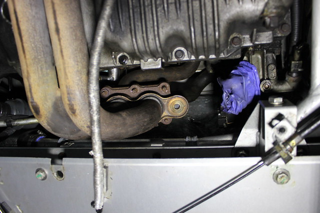
So there’s the gap I’d need to make a section for.

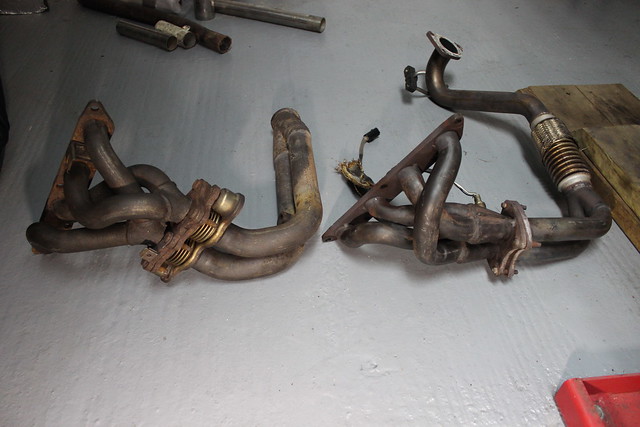
A few pictures to compare the two arrangements.


I was happy I could work with the ZR160 downpipe so made some measurements and guesses at what pipework I’d need to fill the gap to the cat/de-cat.
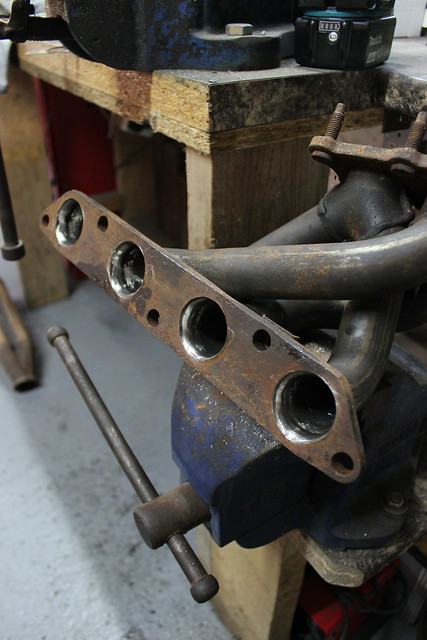
While I was waiting for some stainless pipe to arrive I got on with grinding back the welds on the inside of the manifold. The exhaust tubing is welded to the manifold on the inside meaning it can be a bit of a restriction to flow from the exhaust ports. So simply removing the top edge of the weld bead opens the internal diameter up to help flow. There’s no point getting too carried away with a head that has standard exhaust ports sizes. Maybe if I was fitting this to a ported head I’d be making some measurements of the ports to match the exhaust and if I felt I needed to grind a lot away I’d then add some welds back to the outside of the tube to put some strength back in (I’d probably be fitting a different exhaust manifold if the exhaust ports were opened up that much though). Again, this is for small gains but every little helps.
The proper tools for the job.


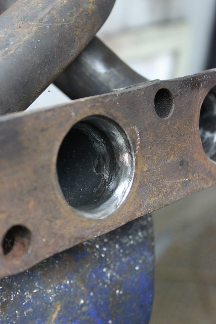
This takes a while but you get there in the end.

Finished.


There is the same problem at the manifold to downpipe join too so I did a little grinding there.


The mating faces of the flanges needed tidying up too.


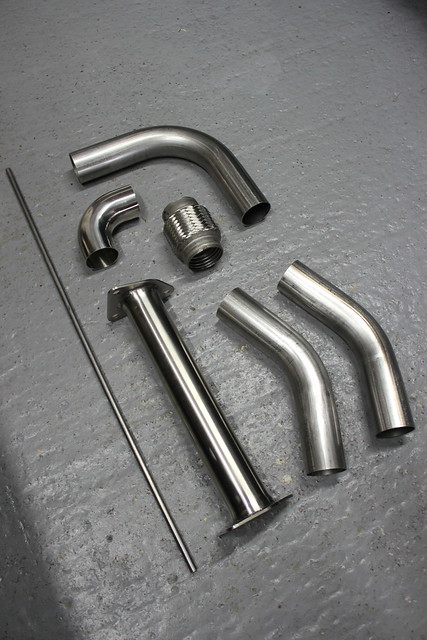
Once the sections of pipe I ordered and a flex section had arrived I could get on with fabricating some exhaust pipe.
Some 57mm/2.25″ stainless pipe, a flexi section, some 10mm stainless bar for the hanger and a stainless de-cat. I bought the de-cat because it was cheaper to buy a de-cat complete with 2 stainless exhaust flanges than it was to buy a single stainless flange!
Some cardboard templates of the bends, not as helpful as I’d hoped they would be but they certainly showed how little space there was to fit the bends and flexi section in with the limited space and larger diameter pipe.

This is gonna be tricky.

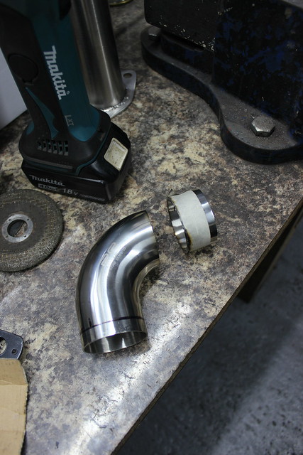
Removing the flange from the de-cat.

The tight 90 bend fitted nicely here meaning I could sit it in place and twist it as required before needing to tack it.
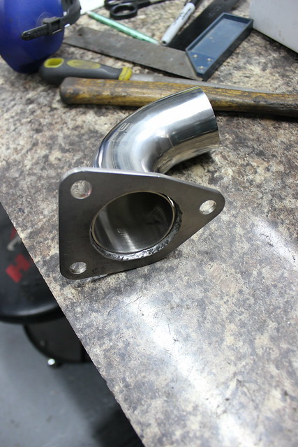

Reckon that’ll do. That’s the easy bit though.

I can spend ages staring at problems like this trying to get convinced about how I’m going to fit the bends in where I need to and not cut anything too short. It’s pretty much impossible to know for sure exactly how it’s going to work though so eventually you just have to start making cuts at your best guess and fitting bits into place.

The quickest way of getting a straight cut when using the angle grinder, wrapping some tape around and cutting along it’s edge.


Some more cutting and slightly hoping for the best.

A bit of a trim on this bit.
Beginning to get somewhere.

Now to squeeze the flexi section into what is only just enough space for it.
The downpipe cut back a little to allow more room for the bends to fit. I can open up the pipe that I join to the downpipe to blend the 2 to 1 section gradually.
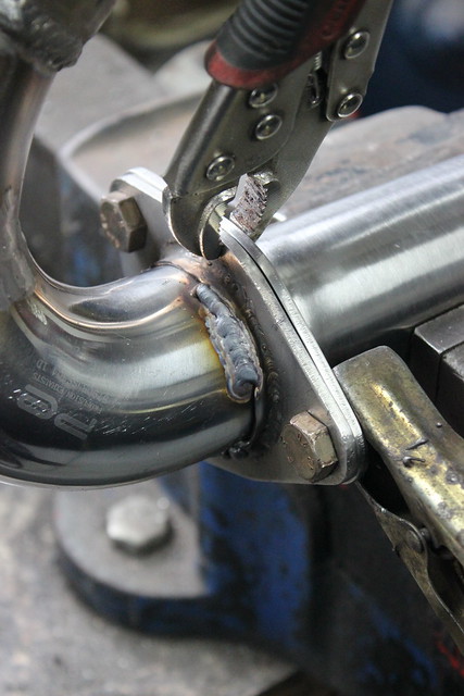
Tacking some bits in place.


Part of the point of this little project was to have a go at some stainless MIG welding. When I’ve welded stainless before I’ve just used mild steel wire but I thought I’d do this properly. So I got some stainless wire and pure argon shield gas. I assumed welding with stainless wire would be just as easy as with mild but have to say it was a bit more tricky or maybe I just needed to slightly re-calibrate my experience of what welder settings to use? Either way I got stuck into some welding while not being particularly happy with the look of most of the welds, they were penetrating fine though and can always be ground back to look a bit more tidy.
Not pretty but it’ll do.

All ground down, wouldn’t normally bother but first bit of MIGing stainless was not up to my standards in the aesthetics department. This was not helped by having real problems with the wire feed, it kept getting stuck, maybe because I only bought a small reel which seems to just not want to spin as freely as the larger ones. This area is where it’s kinda tight around the heat shielding and frame plus I’d need to add a hanger at this point so removing excess weld was kinda helpful for that too.

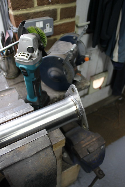
This is more like it! Obviously getting the welder set just right here plus pre-winding some slack into the reel helped the feed work properly.

Flange bolted and clamped to the other flange to help prevent it warping as I weld it.

So far so good.


Last bit of pipe being welding in proper.

Remembering to wind some slack into the reel before each weld. Annoying but it really helped.


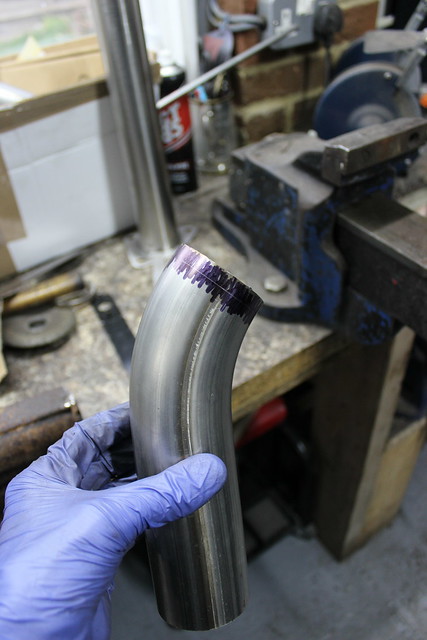
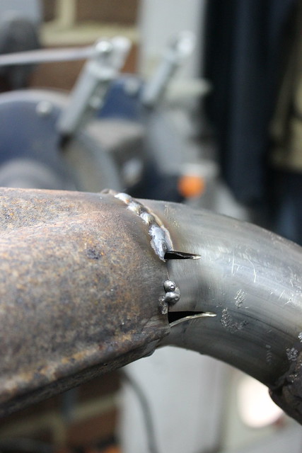
Now the end of the pipe needed some opening out to blend into the downpipe.

After a few cuts and some hammering.


Tack it.

Weld it proper.


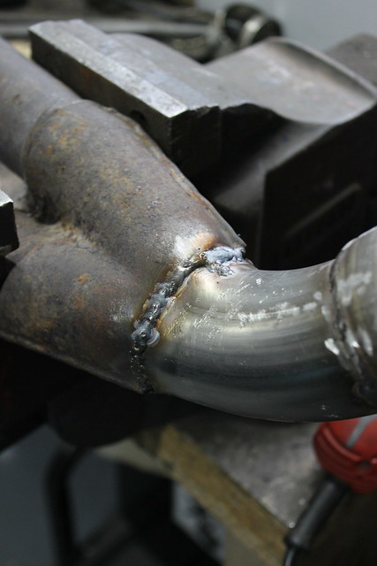


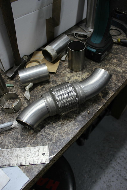
Nearly finished.


Just needs a hanger on it now.
Some 10mm stainless bar with a cut made in it to bend over a section that slides into the rubber hanger meaning the rest of the bar comes down past the exhaust. This bar will just break if you try to bend it too far without putting a cut in it.

Bar cut to length and tacked onto the exhaust, plus the cut I made for the bend welded up.

I drilled a small hole through the bar to add a split pin to help prevent the bar pulling out of the rubber hanger. Not sure if this is necessary but I noticed the previous exhaust hanger always seemed to want to work it’s way across so if this does the same it can only go so far.

Well that’s the actual exhaust finished. For such a short section that needed fabricating it took a little while as it was pretty awkward to get all the bends to work out right and fit in the space. Happy enough with the finished thing though not too keen on the aesthetics of the stainless welds, I guess that’s just MIG welding for you though the thing that makes it frustration is I can get some very nice looking mild MIG welds. As I write this I’ve just bought an AC/DC TIG welder as I got offered it at a price I couldn’t refuse! If only I’d been offered it a few months earlier and I’d have been able to TIG this job and maybe got some ‘internet worthy’ welds for the ‘gram. 😉
Now some other jobs need doing before finally fitting the exhaust…